Arduino

Control :: Electronics :: Solenoids

This is a follow-up to the original post on controlling solenoids with a Pinball Controller’s “Power Driver 16” board. I’m adding some photos to aid with the wiring and assembly, as well as giving a few troubleshooting tips.

Power Driver 16

Overview showing the Power Driver 16 and the Mini RS-485 Master

Click through to see a larger image. This is an overview of the Power Driver 16 and Mini RS-485 Master, showing the inputs, Mini Master output, and connection to the solenoid driver.

Mini Master RS-485

Detail of the Mini Master connections.

Click through to see a larger image. This detail shot shows the inputs to the Mini Master: Orange wire is Power (5V), Blue wire is TX from the Arduino, Black is GND. The outputs of the Mini Master are: White for TX(+) and Black for TX(-).

Power Driver 16 detail

Detail of the RS-485 lines running to the solenoid driver.

This is a detail showing the Mini Master output coming in on the Pinball Controller’s Power Driver 16 port labeled J9. Pin one is Serial +, which gets the White TX(+) wire, and pin 2 is Serial-, which gets the Black TX(-) wire from the Mini Master.

Arduino SPI RS-485

Arduino connection of the SPI interface to the Mini Master RS-485 converter.

Click through for full size image. This shows the Arduino SPI interface to the Mini Master RS-485 converter. It is a three-wire connection, with 5V power, signal and ground.

Arduino Uno pinout

Arduino pinout showing SPI interface pins.


SPI interface uses the GND, MOSI and 5V pins when connecting to the Mini Master RS-485 converter.

Control :: Arduino :: Code

I’ve updated the downloads page (here) with Arduino code for the Game Master Controllers, as well as code for the PinScore Controllers and the Test Circuits.

The Game Master Controllers can be used as-is, or (more likely), as a template for creating your own games. Some are more complicated than others, but they’ve all been recently updated with a common, stable code. They should all have the capability to do multi-player (with the right build-switches set), and the “Miss Adventure” code is designed to to Multi-ball.

Each game has it’s own PinScore controller code. However, Jupiter Crush is the most advanced, so probably would make the best template.

There is also code to test switches, displays and solenoid drivers.


Playfield :: Electronics :: Switches

Switches are probably the single-most important device on a Pinball Playfield, and are fundamental to the game itself. The entire Pinball Machine is essentially an electro-mechanical interaction, with the switch being the all-important middle-man between the ball and the active mechanisms…

Switches also pre-date a lot of the other devices we commonly associate with Pinball, like Flippers, Thumpers, Slingshots, etc. and most machines today still use some manner of the traditional wire-form activated leaf-switch we find on older games.

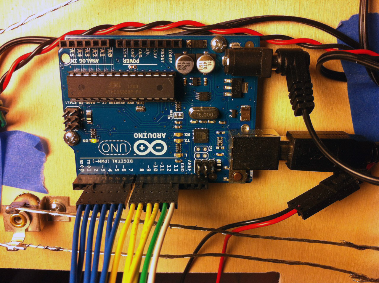
The focus of this blog is on solid-state based Custom Pinball Machines, and one advantage with SS when it comes to switches is that they can be scanned as a matrix. Most SS games since the 70’s have used this technique. With matrix scanning, you can read 40 switches with 5 drive lines and 8 read lines (5×8 = 40), but only use 13 digital I/Os (5+8 = 13). And just to hammer home the math, that saves 27 I/Os (40-13 = 27), putting this in the wheelhouse of a small micro-controller board like the Arduino Uno.

The Layout.

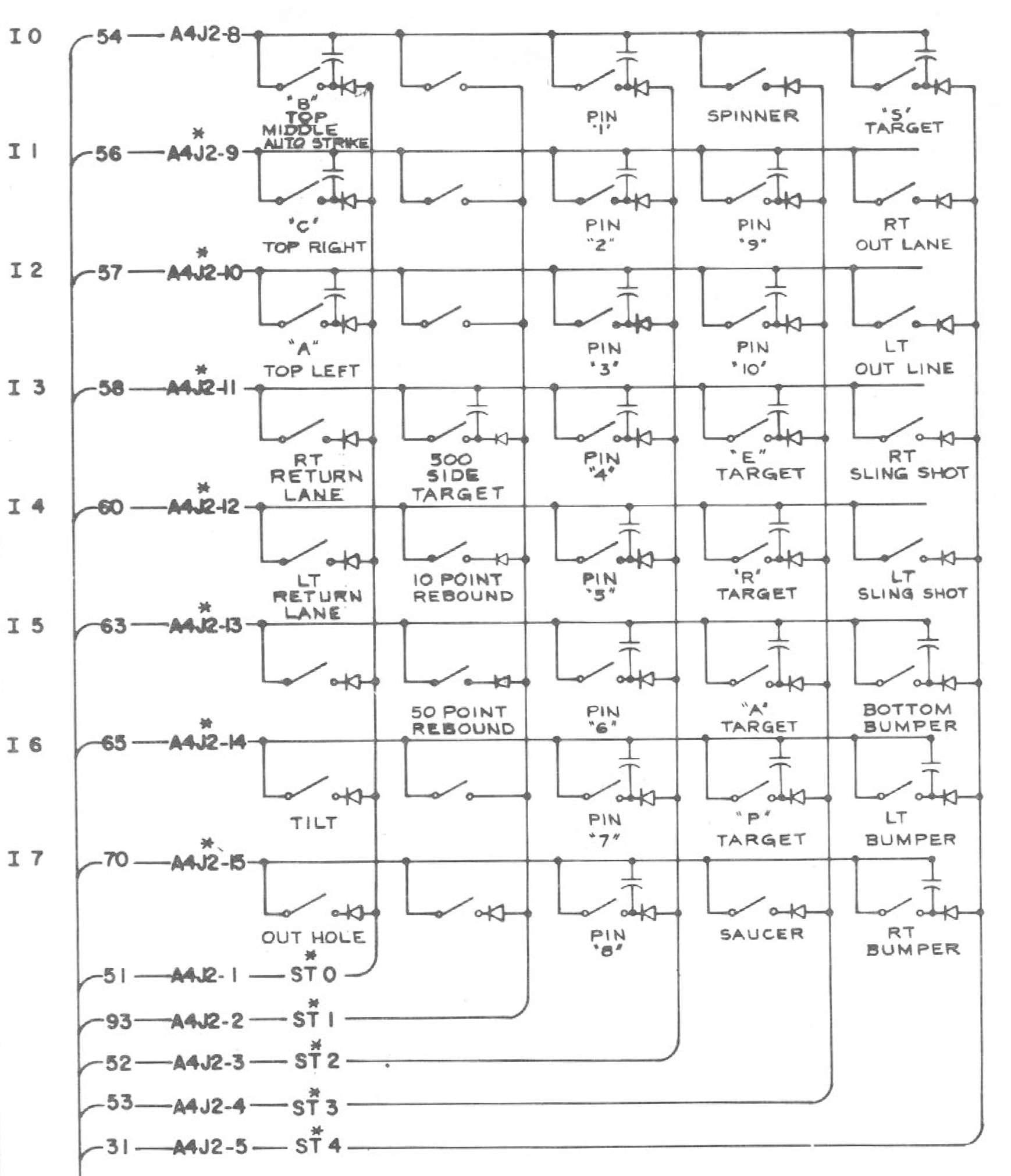
Here’s a typical schematic (below) of a switch matrix from a standard Bally 70’s solid-state (SS) game. I present this because it will serve us well even today since the principles are the same.

Switch matrix schematic

Schematic of a switch matrix designed to be scanned by solid-state electronics. For our Custom Pinball Machine, we will use a micro-controller like the Arduino Uno.


Scanning The Matrix:

In the case above, there are five drive lines and eight sense lines, which we will model for our own design. The process of scanning works like this:

  • All the drive lines are initially held low.
  • The first drive line is switched high.
  • Each of the eight sense lines are read.
  • These values then represent the state of switches 1 thru 8.
  • The first line returns low, and the second line goes high.
  • Again, read in the eight sense lines.
  • These values become the state of switches 9 thru 16.
  • And so on until all 40 switch states are read…

Notice that each switch in the schematic has a diode on the drive side. This prevents “ghosting” in the case of multiple switches being active at the same time. Without it, the current from one drive column could back-feed through any switches active on the same row, in essence driving a second (unintended) column. An active switch on the second column would create a “ghost” activation on the first (real) drive column.

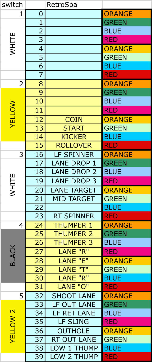
Below is a spreadsheet I usually create during the design of the game, and reference for the assembly and wiring.

Switch matrix excel spreadsheet

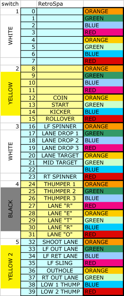
Excel spreadsheet showing switch signal names with drive wire colors and sense line colors.

Most older games made use of two-color striped wire, so there was never a duplicate color combination for any signal. In our case, it’s more feasible to use a limited set of standard colors, and just keep track of where there might be duplicates.

I always create a chart like this early on, giving the switches logical names and grouping them based roughly on where they will be located on the playfield. It helps to use the same name later in the Arduino code that will be doing the scanning.

The Switch.

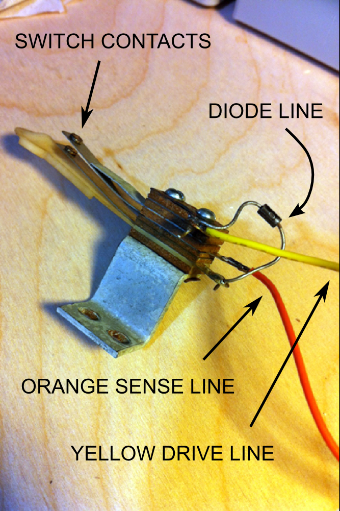
Almost all older games use leaf-switches connected to a wire-form for activation. These usually have three contacts, and the diode mentioned above is mounted directly on the switch. This make wiring easier and more mechanically stable.


Custom Pinball Switch

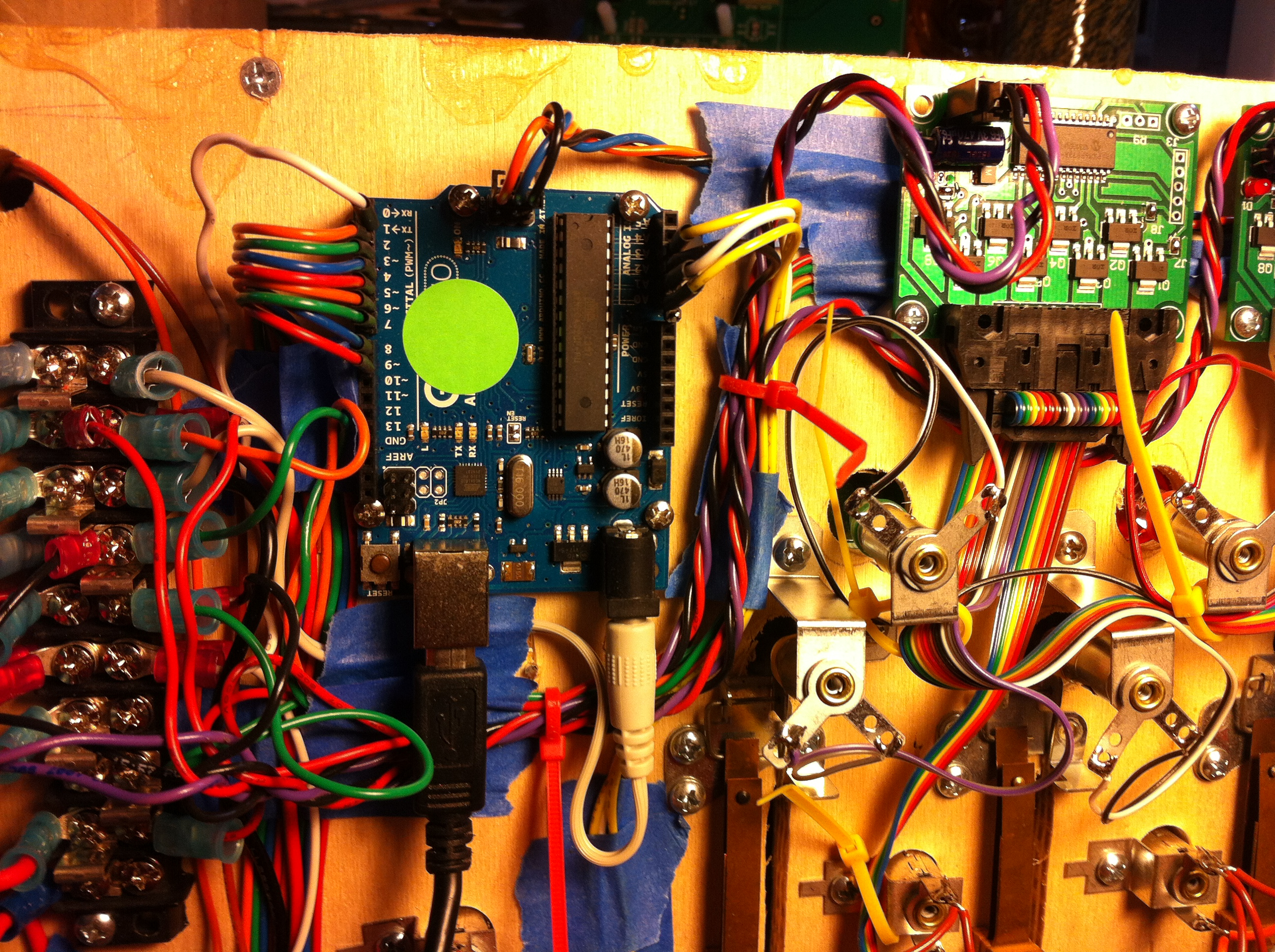
This is a typical “spoon” switch used to activate Thumpers. There is a built-in diode, with the drive wire coming in on the positive side (yellow), and a sense wire on the negative side (orange).

The Code.

Below can be cut-and-pasted into an Arduino project. Use this for testing and diagnostics, or as a reference for creating your own game code.

There are several features to this code aside from just scanning the switch matrix, hopefully it will become clear as you read though it:

  • The code compares the previous state of the switch to the current state to determine if the state is “new”
  • It then rotates the state for the next loop so that current becomes previous.
  • It only call the state “new” if it went low-to-high, you can change this in your own code.
  • It implements a de-bounce timer function, which is adjustable, or just comment it out.
  • Prints the “new” switch state to the serial monitor when switch is activated.
// --------------------------------------------
/*  
INSTRUCTIONS:

This code will scan a 5x8 switch matrix and print the status of new switch states.

CODE FLOW:

  -  Set the first drive line output.
  -  Scan first input.
  -  If state was low, and now high, set new switch flag.
  -  Send message out to Serial Monitor (optional).
  -  Loop through all eight inputs.
  -  Loop through all five drive lines.
  -  Delay.
  -  Repeat.
  
For questions or comments, check the blog:
https://howtobuildapinballmachine.wordpress.com

*/

//  --------------------------
//  BUILD VARIABLES HERE
#define DEBOUNCE_MODE 1
#define SERIAL_MONITOR 1

//  --------------------------
//  VARIABLES
unsigned char j = 0;	//
unsigned char i = 0;	//
unsigned char k = 0;	//

//  --------------------------
//  SWITCHES
unsigned char switchStateNow[40];	// start no digit selected
unsigned char switchStatePrev[40];	// start no digit selected
unsigned char switchNew[40];	//
unsigned char switchDebounce[40];
// --------------------------
// DEFINE SWITCH NAMES HERE
// optional for this test code, but good idea
// if you are going to build on this as a game later.
enum
{
SWITCH_0,
SWITCH_A, // was 1
SWITCH_B, // was 2
SWITCH_C, // was 3
SWITCH_D, // was 4
SWITCH_5,
SWITCH_6,
SWITCH_7,

SWITCH_8,
SWITCH_9,
SWITCH_10,
SWITCH_11,
SWITCH_START,
SWITCH_COIN,
SWITCH_KICKER,
SWITCH_ROLLOVER,

SWITCH_LF_SPINNER, // 16
SWITCH_LANE_DROP_1,
SWITCH_LANE_DROP_2,
SWITCH_LANE_DROP_3, // kicker / shoot again
SWITCH_LANE_TARGET,
SWITCH_MID_TARGET,
SWITCH_22,
SWITCH_RT_SPINNER,

SWITCH_THUMPER_1, // BLACK - ORANGE
SWITCH_THUMPER_2, // BLACK - GREEN
SWITCH_THUMPER_3, // BLACK - BLUE

SWITCH_LANE_R_1,
SWITCH_LANE_E,
SWITCH_LANE_T,
SWITCH_LANE_R_2,
SWITCH_LANE_O,

SWITCH_SHOOT_LANE,
SWITCH_LF_OUT_LANE,
SWITCH_LF_RET_LANE,
SWITCH_LF_SLING,
SWITCH_OUTHOLE,
SWITCH_RT_OUT_LANE,
SWITCH_LOW_1_THUMP, //SHOOT_LANE,
SWITCH_LOW_2_THUMP // 39
};

#define SWITCH_DEBOUNCE_DURATION 10 //10 loops

void setup() 
{  
  pinMode(14,OUTPUT); // analog in used a row drive out
  pinMode(15,OUTPUT);
  pinMode(16,OUTPUT);
  pinMode(17,OUTPUT);
  //pinMode(18,OUTPUT); // if only using four drive lines, no need to set this

  pinMode(2,INPUT); // analog in used a row drive out
  pinMode(3,INPUT); // analog in used a row drive out
  pinMode(4,INPUT); // analog in used a row drive out
  pinMode(5,INPUT); // analog in used a row drive out
  pinMode(6,INPUT); // analog in used a row drive out
  pinMode(7,INPUT); // analog in used a row drive out
  pinMode(8,INPUT); // analog in used a row drive out
  pinMode(9,INPUT); // analog in used a row drive out

  digitalWrite(2,LOW); // pull up on
  digitalWrite(3,LOW); // pull up on
  digitalWrite(4,LOW); // pull up on
  digitalWrite(5,LOW); // pull up on
  digitalWrite(6,LOW); // pull up on
  digitalWrite(7,LOW); // pull up on
  digitalWrite(8,LOW); // pull up on
  digitalWrite(9,LOW); // pull up on

#if (SERIAL_MONITOR == 1)
  Serial.begin(9600);           // start serial for output
#endif

//  --------------------------
//  INITIALIZE SWITCH STATE ON, SINCE WE TRIGGER ON RISING EDGE
  for (j = 0; j < 40; j++) 
  {
    switchStateNow[j] = 1; //
    switchStatePrev[j] = 1;//
    switchNew[j] = 0;
    switchDebounce[j] = 100;
  }
  
} // end setup

void loop() 
{
  //  *****************************************
  //  -----------------------------------------
  //             START READ SWITCH
  //  -----------------------------------------
  //  *****************************************  

  // SET DRIVE LINES HERE
  for (j = 1; j < 5; j++) 
  {
    // START ALL LOW (no signal)
    digitalWrite(14, LOW); // pins 14-17
    digitalWrite(15, LOW); // pins 14-17
    digitalWrite(16, LOW); // pins 14-17
    digitalWrite(17, LOW); // pins 14-17    

    // DRIVE ONE LINE HIGH
    digitalWrite((j+13), HIGH); // pins 14-17

    // WAIT HERE FOR RISE TIME
    delayMicroseconds(400) ;
    
    // START SCAN
    for (i = 0; i < 8; i++) 
    { 
      switchStatePrev[((j*8) + i)] = switchStateNow[((j*8) + i)]; // rotate variable
      switchStateNow[((j*8) + i)] = digitalRead(i + 2); // pins 2-9

      // check for a "new" state
    #if (DEBOUNCE_MODE)
      if ((switchStateNow[((j*8) + i)] == switchStatePrev[((j*8) + i)]) || (switchDebounce[((j*8) + i)] > 0))
    #else
      if ( switchStateNow[((j*8) + i)] == switchStatePrev[((j*8) + i)]) 
    #endif
      {
        switchNew[((j*8) + i)] = 0; // same as old
      } // end if
      
      else // must be new if not old and new equals one
      {
        if (switchStateNow[((j*8) + i)] == 1)
        {
          switchNew[((j*8) + i)] = 1; // new
          
          #if (DEBOUNCE_MODE)
            switchDebounce[((j*8) + i)] = SWITCH_DEBOUNCE_DURATION; // set timer
          #endif
          
          #if (SERIAL_MONITOR == 1)
            Serial.print("Switch = ");
            Serial.print((j*8) + i); // TODO check this formatting later
            Serial.print("\r\n");
          #endif
        }
      } // end else
    } // end for i
  } // end for j    

  #if (DEBOUNCE_MODE)
    for (j = 0; j < 40; j++) 
    {
      if (switchDebounce[j] > 0) 
      {
        switchDebounce[j] -= 1; // ramp down to zero
      }
    }
  #endif

  delay(10) ; // 10ms loop time
  
  // end read switches

//return;// end MAIN LOOP


Cabinet :: Electronics :: Display

In recent years, reproduction components and other products have surfaced to help repair and restore vintage pinball machines. Some of these reproductions make use of the latest technology internally, essentially a re-design that is more reliable than the original. One case in point is the Classic LED Pinball Display from PinScore. We can take advantage of the great work being done on the restoration side, leveraging this market to create our Custom Pinball Machines. But in this case, we need some way to easily interface these devices to whatever control system we happen to be using. Which is the subject of today’s post…

PinScore display

PinScore makes reproduction displays, using the latest technology for higher reliability.

PinScore Display:

If you’re building a four-player game, you can buy a set of these for a little bit of a discount. I usually purchase from Marco Specialties Pinball Parts when I can, a direct link to the products you’ll need can be found here:

PinScore display custom pinball machine

An Arduino can be used to drive a PinScore display, while also communicating serially with a game controller.

Arduino Uno:

The Maker community has already discovered that the Arduino series of boards is an easy and inexpensive way to get into programming with micro controllers. Here are links to get you started:

The Arduino IDE is a free software download, with a large support community, and can be downloaded here.

PinScore display custom pinball machine

Detail shot of Arduino showing connections and pinouts.

Using the parts list above, you should have everything you need to connect the PinScore to the Arduino as shown above and below.

PinScore display custom pinball machine

Detail showing connection side of PinScore with header pinout to Arduino.

I’ve provided some test code at the bottom of the page that can be cut-and-pasted into an Arduino project. The photo below shows the display being mounting into the front of the light board, with the test numbers “123456” loaded. The Arduino project is set up to use the Serial interface, which for diagnostic purposes can be accessed over the same USB programming plug, and the Serial Monitor built into the Arduino IDE.

PinScore display custom pinball machine

Display mounted from the front into a standard Bally score bracket.

Below shows all the displays installed, waiting for the backglass.

PinScore display custom pinball machine

Finished installation showing all five displays and the lit up back-board.

The Arduino code below can be used as a reference in your own controller, or directly as a diagnostic test tool. The procedure to test a unit is as follows:

  • Plug your target board (with PinScore display attached) into your computer via USB.
  • Power the PinScore with external 5V supply.
  • Download the program to the target.
  • Open the Serial Monitor built into the IDE Tools.
  • Type “$pinXyyyyyy” and press return, where X is the number you assigned the display (i.e. player 4), and yyyyyy is the number or score you want to display. For example, “$pin4123456” is what I typed in to display what is in the photos above.
  • If your score is less that six digits, use an underscore. For example, “$pin4_98765” will display the number 98765, with the first digit being blank.
  • If you have a fifth display for Balls/Credits, you would sent something like “$pin5_03_10” for Ball = 3 and Credits = 10.

Arduino code here.

Cut and paste text into a new project, then download to your target device.

//
/*  
INSTRUCTIONS:

Using the serial monitor, type in the header "$PIN" followed by the ID you've chosen
for the PinScore display (ie, 1, 2, 3, 4 etc), and then the actual score for that unit.

EXAMPLE: Typing in "$PIN4100000" to the serial monitor and hitting return should read
the score "100000"  player four's display.

For questions or comments, check the blog:
https://howtobuildapinballmachine.wordpress.com

*/

String inputString = "";         // a string to hold incoming data
boolean stringComplete = false;  // whether the string is complete
unsigned char selectDigit = 0;	// start no digit selected
const unsigned char selectLatch = 12;	// start no digit selected
unsigned char cDataPinScore[8];
unsigned char cPinScore = 4;
unsigned char digitBCD = 0;	// start no digit selected

// ASCII CODE DEFINES
#define ASCII_A 65
#define ASCII_B 66
#define ASCII_C 67
#define ASCII_D 68
#define ASCII_E 69
#define ASCII_F 70
#define ASCII_G 71
#define ASCII_H 72
#define ASCII_I 73
#define ASCII_J 74
#define ASCII_K 75
#define ASCII_L 76
#define ASCII_M 77
#define ASCII_N 78
#define ASCII_O 79
#define ASCII_P 80
#define ASCII_Q 81
#define ASCII_R 82
#define ASCII_S 83
#define ASCII_T 84
#define ASCII_U 85
#define ASCII_V 86
#define ASCII_W 87
#define ASCII_X 88
#define ASCII_Y 89
#define ASCII_Z 90
#define ASCII_EQUAL 61
#define ASCII_DOLLAR 36
#define ASCII_COMMA 44
#define ASCII_CR 13
#define ASCII_LF 10

enum  
{
  LED_ZERO,
  LED_ONE,
  LED_TWO,
  LED_THREE,
  PLAYER_ONE,
  PLAYER_TWO,
  CREDIT_BALLS  
};

#define LED_CHAN PLAYER_ONE // change this to the PLAYER that the unit will be driving

void setup() 
{
  DDRB = B00111111;  // sets Arduino port B pins 0 to 4 as outputs
  DDRD = B11111111;  // sets Arduino port B pins 0 to 4 as outputs

  // initialize serial:
  Serial.begin(9600);

  // reserve 200 bytes for the inputString:
  inputString.reserve(200);

    for (int i = 0; i < 8; i++) 
  {
    cDataPinScore[i] = i + 48;
  }

}

void loop() 
{

// continuously scan the PinScore display, outputing the most recent data
  for (int i = 2; i < 8; i++) 
  {
    selectDigit = i;  

    PORTD = (0); // clear all

    digitalWrite(selectDigit,HIGH);

    PORTB = (cDataPinScore[i-2]- 48); // subracting 48 converts an ASCII char to its equivalent int

    digitalWrite(selectLatch,HIGH);

    delay(3) ;// hold each digit for a period
  }

}

/*
  SerialEvent occurs whenever a new data comes in the
 hardware serial RX.  This routine is run between each
 time loop() runs, so using delay inside loop can delay
 response.  Multiple bytes of data may be available.
 */

void serialEvent() 
{
  while (Serial.available()) 
  {
    // get the new byte:
    char inChar = (char)Serial.read();

    // add it to the inputString:
    inputString += inChar;

    // if the incoming character is a newline, set a flag
    // so the main loop can do something about it:
    if (inChar == '\n') 
    {
      int inputLength = inputString.length();

      if (inputString[0] == ASCII_DOLLAR) // check for header
      {
        cPinScore = inputString[4]; // PinScore id held here

        if (cPinScore == (LED_CHAN + 48)) //4 )
        {
          for (int k = 0; k<6; k++) // acount for numbers less than six digits
  	  {
  	  cDataPinScore[k] = inputString[k + 5];
  	  } // next k

        } // end If received ID matches the one this unit is programmed for

        stringComplete = true;
        inputString = "";

      } // end If first char was $ 

    } // end If new line 

  } // end While// end Sub

Control :: Electronic :: Solenoid

A renewed interest in vintage pinball machines, combined with the growth of the “Maker” movement, has made this an opportune time to build your own pinball machine. Individuals all over the world have simultaneously discovered that we’re now at a technological crossroads: designing and building a pinball machine is a real possibility for the average tinkerer or hobbyist. And a cottage industry has sprung up, providing new and reproduction pinball parts, as well as electronics and control systems, that are ideal platforms for these new Pinball Artists.

The system that I have used the most, and have had the best experience with, has been the “Power Driver 16” from Multimorphic (aka PinballControllers.com).

This system was originally developed to replace older stock controllers, and then evolved to allow modification to the code and thus custom control. Although the Power Driver 16 is meant to be run with a P-ROC system, you can easily connect to almost anything with a serial interface, including an Arduino. This is the approach we will be detailing here…

You will need several things to build the test system outlined:

  • A computer, with the Arduino development environment loaded. You can find it here.
  • An Arduino Uno board, available for purchase many places, including here.
  • A Multimorphic Power Driver 16, from PinballController.com.
  • A Mini Master RS-485 level shifter, also from PinballController.com.
  • Wiring and connectors.
  • Solenoid mechanisms (e.g. Bumpers) to be tested.

The Arduino code detailed in this post uses the Serial Monitor to control the Power Driver 16, and can be found on the Space-Eight.com download page here.

Documentation for using the Power Driver 16 can be found here, or reference the schematics and images below (to be added later).