In recent years, reproduction components and other products have surfaced to help repair and restore vintage pinball machines. Some of these reproductions make use of the latest technology internally, essentially a re-design that is more reliable than the original. One case in point is the Classic LED Pinball Display from PinScore. We can take advantage of the great work being done on the restoration side, leveraging this market to create our Custom Pinball Machines. But in this case, we need some way to easily interface these devices to whatever control system we happen to be using. Which is the subject of today’s post…

PinScore makes reproduction displays, using the latest technology for higher reliability.
PinScore Display:
If you’re building a four-player game, you can buy a set of these for a little bit of a discount. I usually purchase from Marco Specialties Pinball Parts when I can, a direct link to the products you’ll need can be found here:
- PINSCORE Display PS-2518 Set A #PS-2518-A
- Connector .156″ 20 position female #CF15620
- Crimp terminal .156″ Trifurcon #CT156T
- Crimping tool – Molex/Waldom #77-CTW
An Arduino can be used to drive a PinScore display, while also communicating serially with a game controller.
Arduino Uno:
The Maker community has already discovered that the Arduino series of boards is an easy and inexpensive way to get into programming with micro controllers. Here are links to get you started:
- Arduino Uno R3 (Atmega328 – assembled)
- WM2904-ND – Connector housing.
- WM2563CT-ND – Female pins.
- LS150-5 – Power supply, 5V.
- CA-2187 – 2.1mm barrel cable.
The Arduino IDE is a free software download, with a large support community, and can be downloaded here.
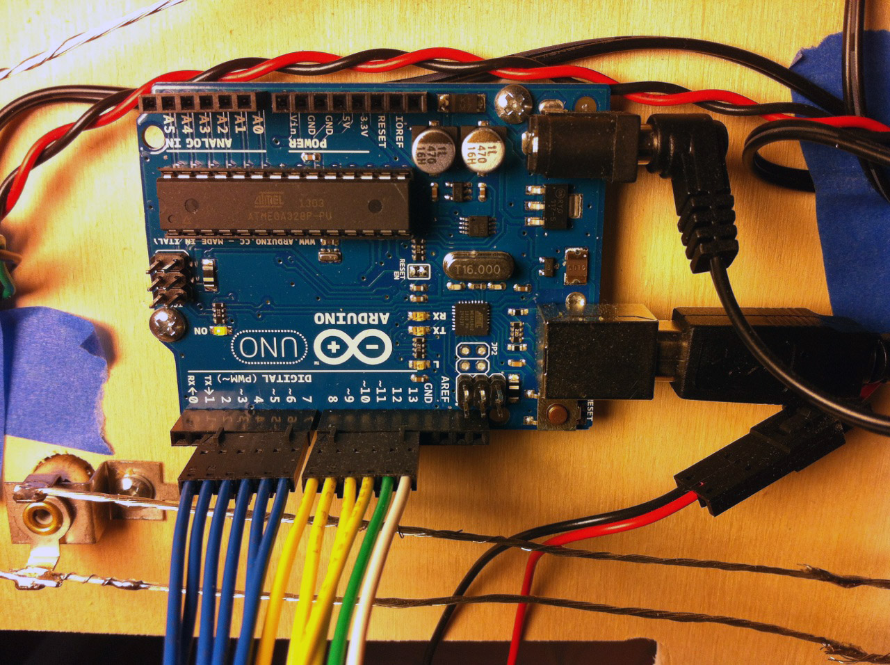
Detail shot of Arduino showing connections and pinouts.
Using the parts list above, you should have everything you need to connect the PinScore to the Arduino as shown above and below.

Detail showing connection side of PinScore with header pinout to Arduino.
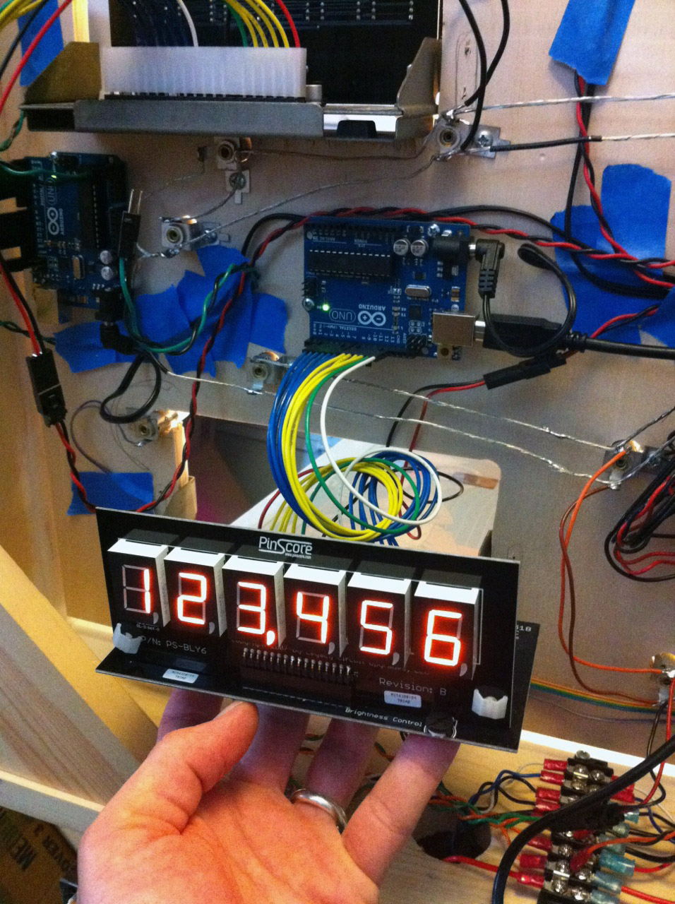
I’ve provided some test code at the bottom of the page that can be cut-and-pasted into an Arduino project. The photo below shows the display being mounting into the front of the light board, with the test numbers “123456” loaded. The Arduino project is set up to use the Serial interface, which for diagnostic purposes can be accessed over the same USB programming plug, and the Serial Monitor built into the Arduino IDE.

Display mounted from the front into a standard Bally score bracket.
Below shows all the displays installed, waiting for the backglass.

Finished installation showing all five displays and the lit up back-board.
The Arduino code below can be used as a reference in your own controller, or directly as a diagnostic test tool. The procedure to test a unit is as follows:
- Plug your target board (with PinScore display attached) into your computer via USB.
- Power the PinScore with external 5V supply.
- Download the program to the target.
- Open the Serial Monitor built into the IDE Tools.
- Type “$pinXyyyyyy” and press return, where X is the number you assigned the display (i.e. player 4), and yyyyyy is the number or score you want to display. For example, “$pin4123456” is what I typed in to display what is in the photos above.
- If your score is less that six digits, use an underscore. For example, “$pin4_98765” will display the number 98765, with the first digit being blank.
- If you have a fifth display for Balls/Credits, you would sent something like “$pin5_03_10” for Ball = 3 and Credits = 10.
Arduino code here.
Cut and paste text into a new project, then download to your target device.
//
/*
INSTRUCTIONS:

Using the serial monitor, type in the header "$PIN" followed by the ID you've chosen
for the PinScore display (ie, 1, 2, 3, 4 etc), and then the actual score for that unit.

EXAMPLE: Typing in "$PIN4100000" to the serial monitor and hitting return should read
the score "100000"  player four's display.

For questions or comments, check the blog:
https://howtobuildapinballmachine.wordpress.com

*/

String inputString = "";         // a string to hold incoming data
boolean stringComplete = false;  // whether the string is complete
unsigned char selectDigit = 0;	// start no digit selected
const unsigned char selectLatch = 12;	// start no digit selected
unsigned char cDataPinScore[8];
unsigned char cPinScore = 4;
unsigned char digitBCD = 0;	// start no digit selected

// ASCII CODE DEFINES
#define ASCII_A 65
#define ASCII_B 66
#define ASCII_C 67
#define ASCII_D 68
#define ASCII_E 69
#define ASCII_F 70
#define ASCII_G 71
#define ASCII_H 72
#define ASCII_I 73
#define ASCII_J 74
#define ASCII_K 75
#define ASCII_L 76
#define ASCII_M 77
#define ASCII_N 78
#define ASCII_O 79
#define ASCII_P 80
#define ASCII_Q 81
#define ASCII_R 82
#define ASCII_S 83
#define ASCII_T 84
#define ASCII_U 85
#define ASCII_V 86
#define ASCII_W 87
#define ASCII_X 88
#define ASCII_Y 89
#define ASCII_Z 90
#define ASCII_EQUAL 61
#define ASCII_DOLLAR 36
#define ASCII_COMMA 44
#define ASCII_CR 13
#define ASCII_LF 10

enum
{
  LED_ZERO,
  LED_ONE,
  LED_TWO,
  LED_THREE,
  PLAYER_ONE,
  PLAYER_TWO,
  CREDIT_BALLS
};

#define LED_CHAN PLAYER_ONE // change this to the PLAYER that the unit will be driving

void setup()
{
  DDRB = B00111111;  // sets Arduino port B pins 0 to 4 as outputs
  DDRD = B11111111;  // sets Arduino port B pins 0 to 4 as outputs

  // initialize serial:
  Serial.begin(9600);

  // reserve 200 bytes for the inputString:
  inputString.reserve(200);

    for (int i = 0; i < 8; i++)
  {
    cDataPinScore[i] = i + 48;
  }

}

void loop()
{

// continuously scan the PinScore display, outputing the most recent data
  for (int i = 2; i < 8; i++)
  {
    selectDigit = i;

    PORTD = (0); // clear all

    digitalWrite(selectDigit,HIGH);

    PORTB = (cDataPinScore[i-2]- 48); // subracting 48 converts an ASCII char to its equivalent int

    digitalWrite(selectLatch,HIGH);

    delay(3) ;// hold each digit for a period
  }

}

/*
  SerialEvent occurs whenever a new data comes in the
 hardware serial RX.  This routine is run between each
 time loop() runs, so using delay inside loop can delay
 response.  Multiple bytes of data may be available.
 */

void serialEvent()
{
  while (Serial.available())
  {
    // get the new byte:
    char inChar = (char)Serial.read();

    // add it to the inputString:
    inputString += inChar;

    // if the incoming character is a newline, set a flag
    // so the main loop can do something about it:
    if (inChar == '\n')
    {
      int inputLength = inputString.length();

      if (inputString[0] == ASCII_DOLLAR) // check for header
      {
        cPinScore = inputString[4]; // PinScore id held here

        if (cPinScore == (LED_CHAN + 48)) //4 )
        {
          for (int k = 0; k<6; k++) // acount for numbers less than six digits
  	  {
  	  cDataPinScore[k] = inputString[k + 5];
  	  } // next k

        } // end If received ID matches the one this unit is programmed for

        stringComplete = true;
        inputString = "";

      } // end If first char was $

    } // end If new line

  } // end While

} // end Sub

I see you used a seperate controller for each display. Some of the earlier Williams machines had a master display board that ran all 5 displays. Do you think there might be a way an uno could control the master display board on earlier machines?
Yeah, using five Arduino Uno’s just for the displays is WAY overkill, especially since the entire custom game is essentially run on a single Arduino…
With that said, the Uno is only a fraction of the cost of the display itself, so not a huge hit here. And the LED display is driven by parallel lines that require constant refresh, so that eats up all the pins and cycle time of a single Arduino.
The real solution here (and I’ve talked to the PinScore guy about this) is to simply add a $5 (or less) micro controller to the existing design, and have it accessible over SPI or I2C. There is a lot of potential to make it simpler, but what we’re really leveraging here is the cost savings of something marketed towards the vintage repair and restoration market (which is much bigger than the custom market).
Bottom line, an Arduino on it’s own doesn’t have enough free pins to control all five displays. Some additional hardware would be needed…