Month: September 2014

Control :: Electronics :: Solenoids

This is a follow-up to the original post on controlling solenoids with a Pinball Controller’s “Power Driver 16” board. I’m adding some photos to aid with the wiring and assembly, as well as giving a few troubleshooting tips.

Power Driver 16

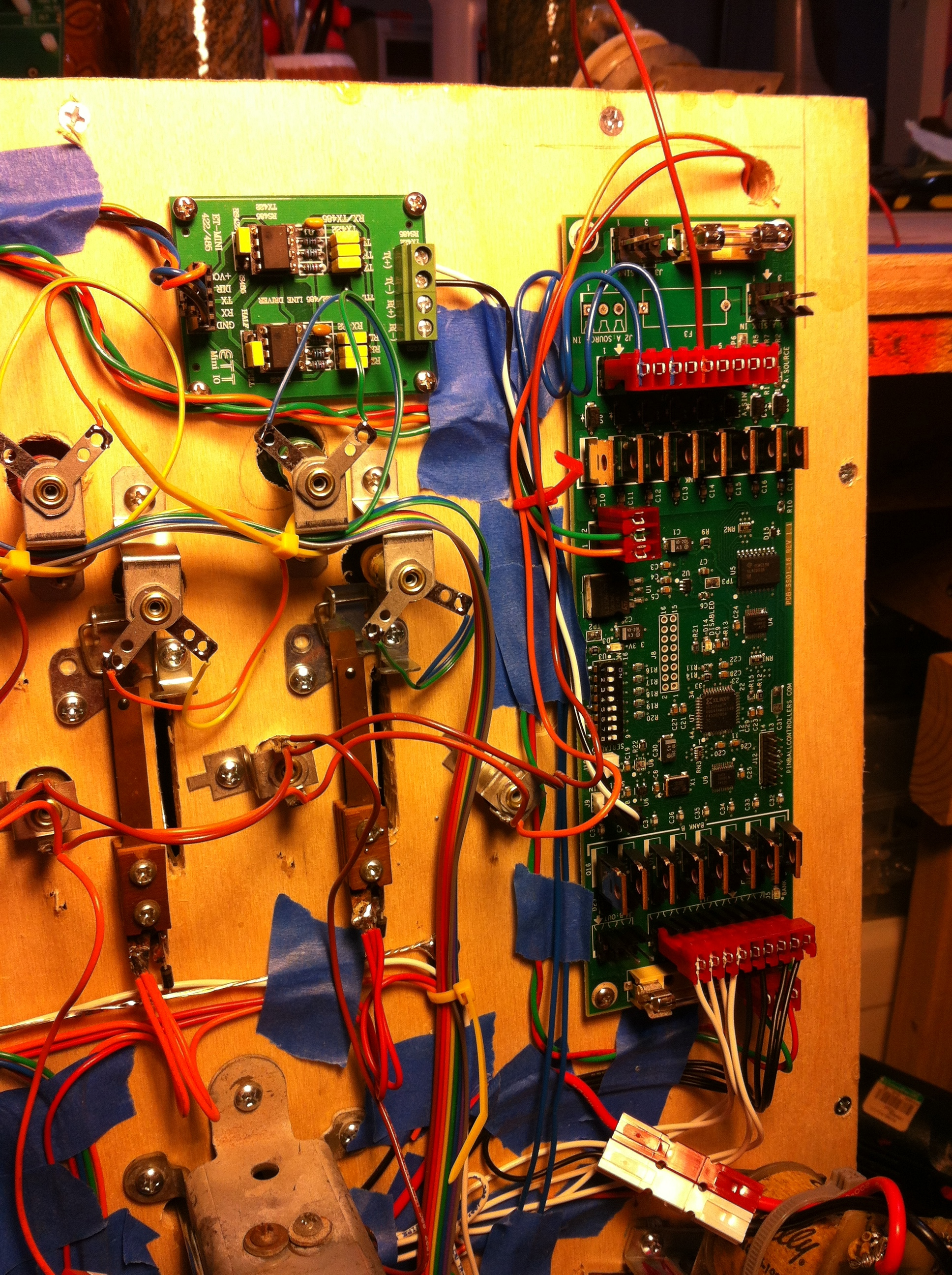
Overview showing the Power Driver 16 and the Mini RS-485 Master

Click through to see a larger image. This is an overview of the Power Driver 16 and Mini RS-485 Master, showing the inputs, Mini Master output, and connection to the solenoid driver.

Mini Master RS-485

Detail of the Mini Master connections.

Click through to see a larger image. This detail shot shows the inputs to the Mini Master: Orange wire is Power (5V), Blue wire is TX from the Arduino, Black is GND. The outputs of the Mini Master are: White for TX(+) and Black for TX(-).

Power Driver 16 detail

Detail of the RS-485 lines running to the solenoid driver.

This is a detail showing the Mini Master output coming in on the Pinball Controller’s Power Driver 16 port labeled J9. Pin one is Serial +, which gets the White TX(+) wire, and pin 2 is Serial-, which gets the Black TX(-) wire from the Mini Master.

Arduino SPI RS-485

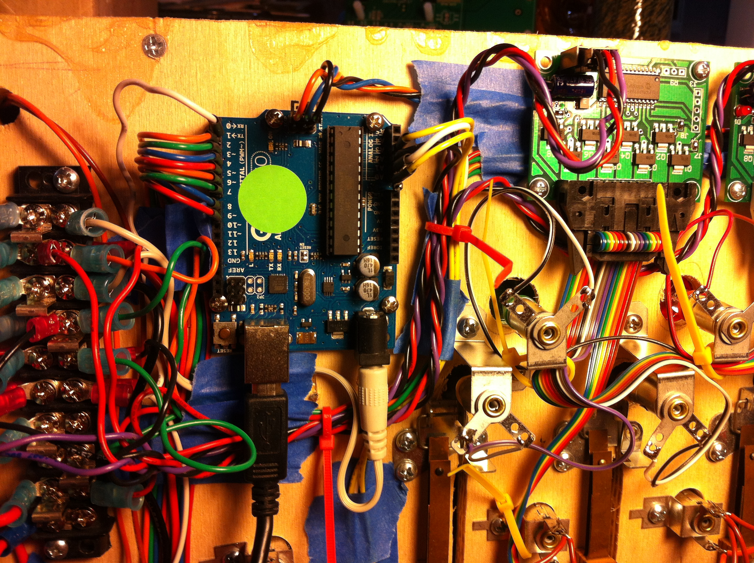
Arduino connection of the SPI interface to the Mini Master RS-485 converter.

Click through for full size image. This shows the Arduino SPI interface to the Mini Master RS-485 converter. It is a three-wire connection, with 5V power, signal and ground.

Arduino Uno pinout

Arduino pinout showing SPI interface pins.


SPI interface uses the GND, MOSI and 5V pins when connecting to the Mini Master RS-485 converter.

Control :: Arduino :: Code

I’ve updated the downloads page (here) with Arduino code for the Game Master Controllers, as well as code for the PinScore Controllers and the Test Circuits.

The Game Master Controllers can be used as-is, or (more likely), as a template for creating your own games. Some are more complicated than others, but they’ve all been recently updated with a common, stable code. They should all have the capability to do multi-player (with the right build-switches set), and the “Miss Adventure” code is designed to to Multi-ball.

Each game has it’s own PinScore controller code. However, Jupiter Crush is the most advanced, so probably would make the best template.

There is also code to test switches, displays and solenoid drivers.


Cabinet :: Design :: Head

This Pinball Head design is one that I’ve used on all three of my Custom Pinball Machines, and will work with the lower-angled retro-looking cabinets, as well as the steeper multi-level ones. The head has a thinner profile than older games, mainly because less room is needed for electronics and wiring. The angled trim pieces, however, keep the vintage look.

Head assembly CAD model

SolidWorks screenshot of of Head assembly.

This SolidWorks model is available on the downloads page, as well as DXFs and SVGs of the templates you see here.

Custom Pinball Head

Diagram of individual parts for the Head, along with assembly views.

Above is a diagram of the parts needed to make the head, along with assembly views. These pieces are cut from either 1×4 or 1×6 pine, which is easy to find at your local hardware store. The light board is 1/2″ plywood, but doesn’t need to be the same high quality as the playfield. A piano hinge is used to attach the light board to the head, allowing access to the back. My preference for score displays is to use vintage brackets, which I’ve included in the template as an example.

Cabinet with Head

Extra trim parts and brackets needed to complete Cabinet assembly and Head attachment.

There are several extra trim pieces needed to complete the Cabinet and Head assembly. A piece of 1×4 pine stock is cut down to 2.375 wide, and serves to fill the gap between the head and cabinet, as well as act as a corner brace for the rear corners. A 1.75″ long block of 2×2 pine (which is really 1.5″x 1.5″) is used to locate and support the leg bracket during assembly, and also serves as corner reinforcement.

Cabinet :: Design :: Templates

My most recent Custom Pinball Machine utilized a multi-level playfield, which requires the steeper slope you typically see on more modern cabinets. I’ve posted templates for this design for those that are either looking for a modern feel, or need the extra headroom for flying wire-forms or alpha-ramps (or just an old-school upper level playfield).

I call this latest pin “Miss Adventure”, so all the files will have the initial MA right after the date code. These can all be found on the download page. Please understand ahead of time that the Cabinet depth is designed to work with Gottlieb lockdown bar hardware, and a Custom Head (template for this to follow in the next post).

Note that, as in the previous post, the front corners are intended to be mitered for a high-quality professional look. If you’re not going to do this step for whatever reason, be sure to take off an extra 3/4″ cut (indicated by the blue dash in the SVG and DXF files), but only take this off either 1) front of both left and right side pieces (preferred) or 2) both edges of the front piece (less-preferred).

SolidWorks ScreenShot

This is a SolidWorks screenshot for a two-level Custom Pinball Cabinet

This template is designed to be mostly cut from a single sheet of 4’x8′ plywood, 3/4″ thick. Birch top is usually relatively cheap while providing a quality finish. Some other minor pieces are needed, which I usually cut from pine stock. I’ll detail this in the next post related to the Head fabrication.

Plywood template for Custom Pinball Cabinet

Template for cutting Custom Cabinet pieces from a single sheet of 4’x8′ Birch plywood.