If you are contemplating building your own machine, then you probably already know a good bit about how pinball machines work. It’s basically series of electro-mechanical events where a steel ball activates a switch, which in turn fires a solenoid that drives a mechanism, sending the ball off in some other direction where it most likely hits another switch, and so on and so on…
The Flippers are the only real interface to the game: You manually activate a switch that fires a solenoid, which then drives the flipper mechanism… The issue that becomes apparent with Flippers is that you want high-power (and high current) when you’re hitting the ball, but you don’t want to burn out your flipper coils if you hold the buttons too long. These problems have been solved during the long evolution of Pinball, with somewhat complicated results.
It’s understandable that there are often questions about connecting and firing Flippers; With their double-wound coils, multiple recirculation diodes, and end-of-stroke (EOS) switches, it’s easy to get confused if you’re hooking them up for the first time. And to make things more complex, today’s modern control systems have the ability to do many more things, like fire the “power” and “hold” coils independently, apply “patter” to the coils, feed the EOS switch into the controller as a normal switch, or even bypassed it completely.
I’m not going to make a case for what is the best way, but I will elaborate on each of the pro’s and con’s and let you decide what works best for your own Custom Pinball Machine…
Background on the standard 70’s- or 80’s-style setup:
Most early games fired the Flippers directly off of the cabinet flipper buttons, using high-power contact switches. In addition to this, there was some sort of relay in series with the circuit that could enable and disable the flippers between games, or even between balls. Here’s a diagram of a standard vintage-style setup:
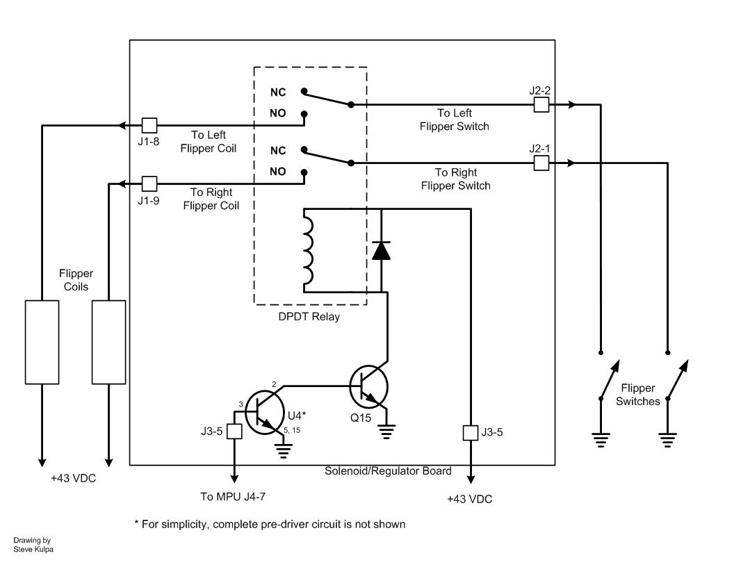
Typical vintage circuit for enabling pinball flipper mechs.
And typical vintage-style EOS switch setup and function:
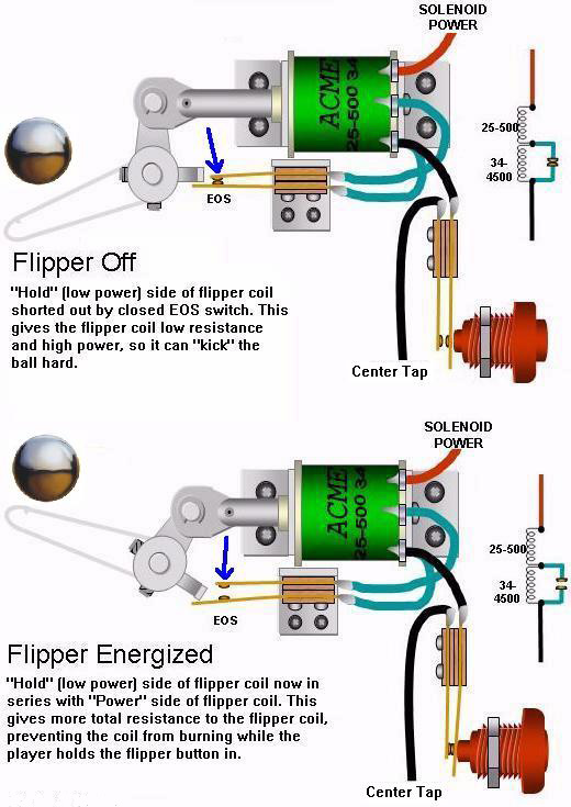
Typical End-of-Stroke switch setup and function.
In the above diagram, the EOS switch is Normally Closed (NC) before activation. The switch is shorting out the “Hold” coil, which is a higher resistance and would otherwise limit the current. One the Flipper has reached full stroke, the EOS switch opens, adding the “Hold” coil to the circuit. This reduces the current while maintaining enough of an electro-magnetic field to keep the solenoid in position. On a side note, the typical convention for labeling coils is to indicate the wire gauge, followed by the number of turns. So “25-500” is 500 turns of 25Ga magnet wire. The hold coil is labeled “34-4500”, so 4500 turns of 34Ga magnet wire. Low gauge is thicker wire, with less resistance and higher current carrying ability. Resistance also increases with length. So more turns at a higher gauge will yield a much higher resistance than fewer turns at a lower gauge, even if the same amount of copper is used.
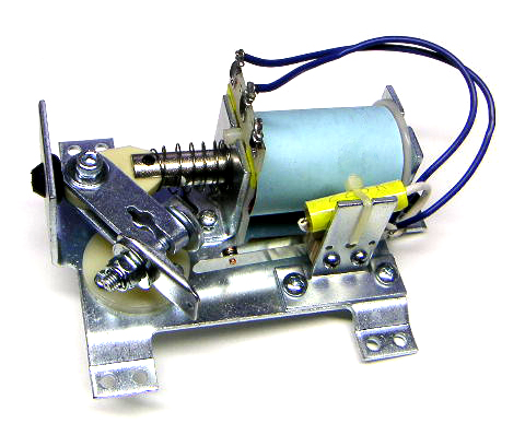
Speaking from personal experience, about half of my Custom Pinball games use this type of setup. The specific relay (and corresponding socket) that I have used to enable the flippers can be found here:

Standard K10 form-factor relay, DPDT suitable for pinball.

Typical K10 relay socket with terminal connections.
You have a couple of options in wiring up this circuit. I like to have the relay on the high-voltage side of the flipper coils, and use the cabinet buttons to switch the ground side of the coil.
If you’re interested in using this old-school method, or possible have scavenged parts from vintage machines, here are a couple links that describe how these older circuits work, and how to properly repair older Flippers:
Old-school Advantages:
Zero latency from button push to firing the flippers. And, only one solenoid driver channel is used, just for the relay.
Old-school Disadvantages:
As simple as the circuit is, it can be a lot of wiring to get power, ground, buttons, flippers, and solenoid driver lines all to a central relay. Power of the flippers are not independently adjustable.
Variations on the Old-school circuit:
From a power supply standpoint, one concern with flippers is that their high-power coils produce large current surges (see the previous blog post for more info on power supplies). This could become a problem particularly on multiple-flipper games. However, I have wired four-flipper games in parallel without any issues. If it is a concern when building your own Custom Pinball Machine, there are clever variants that uses the EOS switches to stagger the firing of the upper and lower flippers. The advantage being that the surge current is spread out over time, so each flipper gets the full power available. Primary flipper requires a DPST leaf-switch, circuit diagram here:

Staggered firing of multiple flipper coils using the primary EOS switch, reduces surge current.
Modern Systems:
If you’re building a Custom Pinball Machine, the controllers and drivers available today allow for independent firing of both the “power” and “hold” coils, or they can adjust the duty cycle of the voltage to the solenoid so that only a single “power” coil is needed. The EOS switch can be used to tell the controller to go to a much lower duty-cycle, or the EOS switch can be bypassed completely and a timer function used instead to switch to a low-power mode. This modern technique uses PWM, sometimes called “patter”. Here is a good breakdown of the various methods that can be used today:
Modern Advantages:
It’s much easier to wire flippers directly to the driver, and have cabinet buttons go to the controller. I currently have two Custom Pinball Machines wired this way, and I can see how the ease of wiring justifies the downsides. Plus, you have full control over flipper power, and could even manipulate the power as part of the game rules.
Modern Disadvantages:
Having the Flipper buttons sent to the controller, and then the controller signal sent to the driver, can introduce latency (that is, a significant delay between pushing the button and seeing something happen). This is by far the most commonly cited disadvantage. However, I can say from personal experience that it’s barely noticeable (or not detectable at all), even with a relatively low-speed controller like an Arduino. With that said, there are other potentially more critical disadvantages… Eliminating the EOS circuit is not “Fail Safe”. Having the high-power coil under computer control could lead to problems, especially during development and testing, or as a machine gets older and less reliable.
Another disadvantage is that configurations firing two coils per Flipper (independant “power” and “hold”) can eat up available driver channels pretty quickly, especially on multi-flipper games. But this would only be a corner case where the EOS switch was eliminated, while retaining the “hold” coil (as in situations where PWM “patter” drive is not an option).
Where to Buy:
Aside from eBay, and especially if you want new hardware, the best places to buy Pinball Flipper Mechs are from Marco Specialty or Pinball Life:
- Marco Specialty: Stern Flipper Assembly 500-6543-04
- Pinball Life: Bally Flipper Assembly pbl_C-13174-R_C-13174-L
Reproduction Bally Flipper Mech available from Pinball Life.

Reproduction Stern Flipper Mech from Marco Specialties


